Door switch overview
- The door is controlled by a single pole, centre off SPDT switch (open - auto - close).
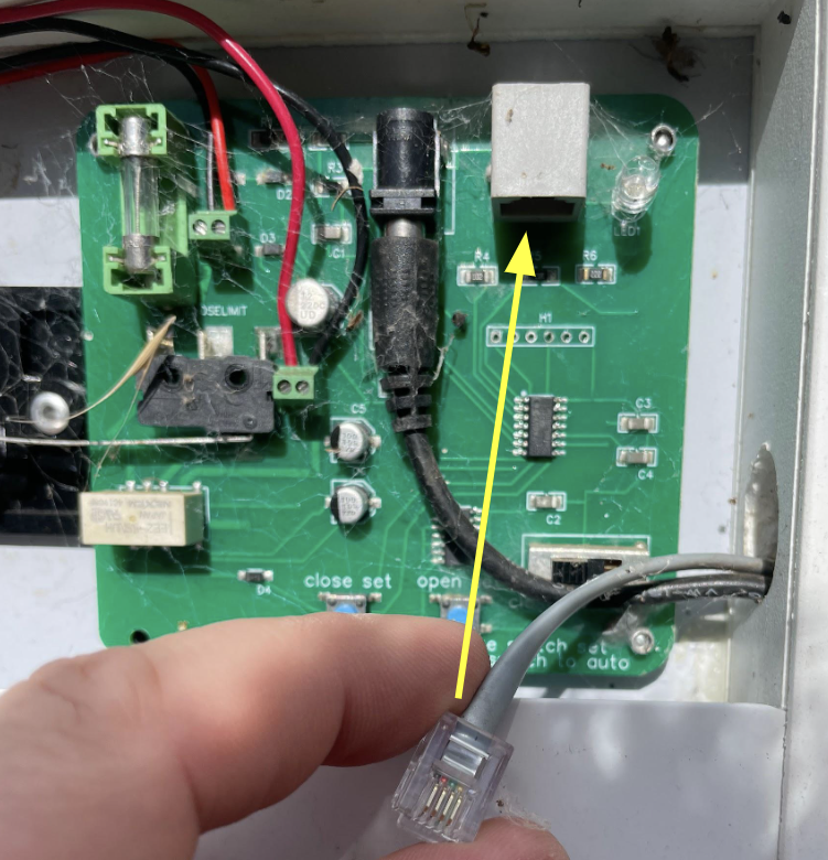
- Conveniently the switch is wired in using a RJ14 cable
This modification is therefore non-destructive as we can wire a new RJ14 cable into the relay HAT for the Pi and plug this into the door controller.
Failure modes
There are two ways the door can be configured depending on your primary use case
- fallback auto - fall back to the light sensor if the computer fails
- fallback close - close the door if the computer fails
Our chickens are free range so we have the relay wired up to revert to auto light sensor operation.
The main risk with this is that foxes can be crepuscular, diurnal, nocturnal or cathemeral which can lead to undesirable opening times.
The benefit being that if the computer were to fail during the day, the chickens are not locked out of the coop.
Wiring details
Only 3 of the 4 RJ14 wires are used when connected to the switch
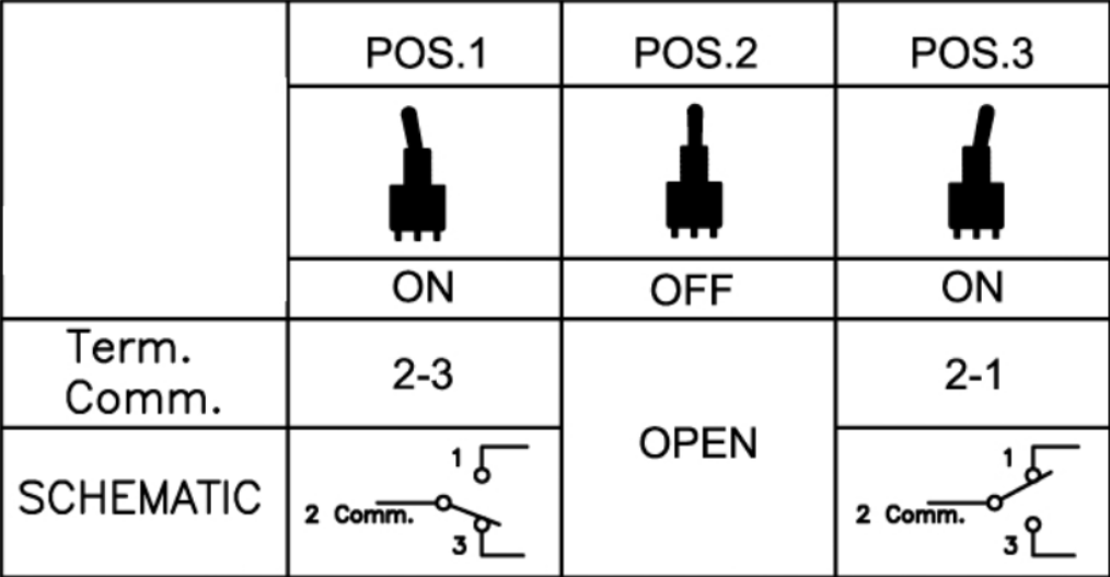
- Closed == Red + Green
- Sensor == no connection
- Opened == Red + Yellow
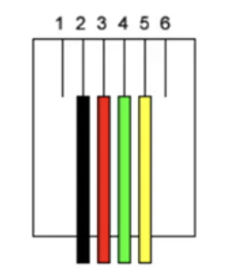
So given the red wire is common but needs to be connected to both relay modules, after stripping the RJ45 cable I used the spare black wire as a bridge.
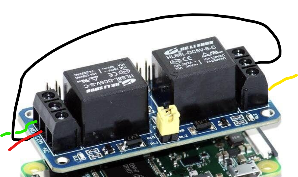
- NO (Normally Open) Switch = Stays in open state, circuit disconnected, unless the relay is active
- NC (Normally Closed) Switch = Stays in closed state, circuit active, unless the relay is active
The wiring in the diagram represents fallback to auto / sensor, both yellow and green wires connected to the NO terminal.
To fallback to a closed state on failure then the green wire should be moved to the NC terminal. NOTE: You will have to update the scripts to expect this as closed relay inactive will now close the door